Kohler Command PRO 999cc Torque Specs
Cylinder head bolt torque at a glance
- CH940-CH1000 (horizontal shaft)415 in-lb≈ 34.6 ft-lbHigh
- CV940-CV1000 (vertical shaft)415 in-lb≈ 34.6 ft-lbHigh
HighMediumLow= how many independent sources agree
The in-lb/ft-lb figure on this page is Kohler's own printed number, not a conversion. Kohler prints N·m first, then the inch- or foot-pound equivalent in parentheses; the N·m figure is quoted in each row's note. The oil drain plug, flywheel screw and spark plug are the only rows Kohler prints in foot-pounds in both manuals; every other row is inch-pounds, including the 415 in-lb final head bolt figure.
The Command PRO CH940-CH1000 (horizontal shaft) and CV940-CV1000 (vertical shaft) are Kohler's 999cc commercial engines -- a different, larger platform from the CH620-CH750/CV620-CV750 V-Twins on Kohler's other torque page, with noticeably higher figures on nearly every shared… Read the rest ›
fastener. This page covers the carbureted engines only -- the ECH/ECV 940-980 EFI variants are covered by a separate manual that could not be found, so they are not covered here. CH and CV are transcribed from their own separate manuals below and kept separate throughout: a handful of fasteners carry genuinely different values between the two, and several exist in only one manual.
Where these numbers come from. 115 published figures, 4 confirmed gaps, every source named. How we checked ›
CH figures come from Kohler's "CH940-CH1000 Service Manual," form 62 690 01 Rev. O (PDF dated 2022-04-27/05-04); CV figures come from the companion "CV940-CV1000 Service Manual," form 62 690 02 Rev. N, same dates -- both hosted directly at resources.kohler.com. Both manuals cover carbureted engines only: "EFI" appears in both only in the EFI Service Kit tool listing, and no service manual for the ECH/ECV 940-980 EFI variants was found (62_690_03/04 return 404 at Kohler's own domain) -- those are not covered by this page. Every table cell spans all four model numbers (940/960/980/1000) in both manuals; no torque value differs by displacement within either manual. One real internal disagreement surfaced and is shown, not resolved: the CV manual's breather cover fastener is 12.4 N·m in the torque table but 12.5 N·m in the reassembly procedure (the CH manual is internally consistent at 12.4 N·m in both places). The rocker arm screw row in both manuals is identified ONLY by a screw pictogram -- no text label, part number, or length is printed anywhere in either document -- so this page describes them as "shorter screw" and "longer screw" exactly as Kohler's pictogram shows, and does not reuse the "black/silver" screw wording from the site's existing CH620-CH750/CV620-CV750 page, which is a different engine family with different screws and different torques. Neither manual publishes a blade, PTO, clutch, deck or spin-on oil filter torque -- both are recorded as confirmed gaps. Kohler prints N·m first with the inch- or foot-pound figure in parentheses; the in-lb/ft-lb shown on this page is Kohler's own printed figure in every row, not a conversion.
Kohler Command PRO CH940-CH1000 (horizontal shaft)999cc Manufacturer-published
series CH940, CH960, CH980, CH1000Covers Kohler service manual form 62 690 01 Rev. O (2022), carbureted engines only -- the ECH940-ECH980 EFI variants are not covered by this… More about this engine ›
manual or this page. Every torque cell in Kohler's table spans all four model numbers; none differs by displacement.
| Fastener | Torque | Where it comes from |
|---|---|---|
| blower housing / sheet metal M6 screw, new untapped hole (casting)M6 | 95 in-lb≈ 7.9 ft-lbHigh | 10.7 N·m (95 in. lb.) -- form 62 690 01 Rev. O, p.14. |
| blower housing / sheet metal M6 screw, used tapped hole (casting)M6 | 65 in-lb≈ 5.4 ft-lbHigh | 7.3 N·m (65 in. lb.) -- form 62 690 01 Rev. O, p.14. |
| blower housing / sheet metal M6 screw, new extruded hole (sheet metal)M6 | 22 in-lb≈ 1.8 ft-lbHigh | 2.5 N·m (22 in. lb.) -- form 62 690 01 Rev. O, p.14. |
| blower housing / sheet metal M6 screw, used extruded hole (sheet metal)M6 | 18 in-lb≈ 1.5 ft-lbHigh | 2.0 N·m (18 in. lb.) -- form 62 690 01 Rev. O, p.14. |
| blower housing / sheet metal M6 screw, mounting clip (valley baffle)M6 | 22 in-lb≈ 1.8 ft-lbHigh | 2.5 N·m (22 in. lb.) -- form 62 690 01 Rev. O, p.14. |
| intake manifold mounting fastener (torque in 2 increments) | 200 in-lb≈ 16.7 ft-lbHigh | Torqued in 2 stages: final 200 in. lb. Why ›(22.6 N·m); initial 150 in. lb. (16.9 N·m). Sequence printed on p.79 of the manual (not reproduced here) -- form 62 690 01 Rev. O, p.14. |
| carburetor / air cleaner mounting nut | 100 in-lb≈ 8.3 ft-lbHigh | 11.3 N·m (100 in. lb.) -- form 62 690 01 Rev. O, p.14. |
| carburetor fuel bowl screw | 22 in-lb≈ 1.8 ft-lbHigh | 2.5 N·m ± 0.3 (22 in. lb. ± 3 in. lb.) -- form 62 690 01 Rev. O, p.14. Why ›The CV manual states the same metric tolerance as a slightly different English figure; see the CV engine below. |
| air cleaner mounting screw (into intake manifold) | 100 in-lb≈ 8.3 ft-lbHigh | 11.3 N·m (100 in. lb.) -- form 62 690 01 Rev. O, p.14. |
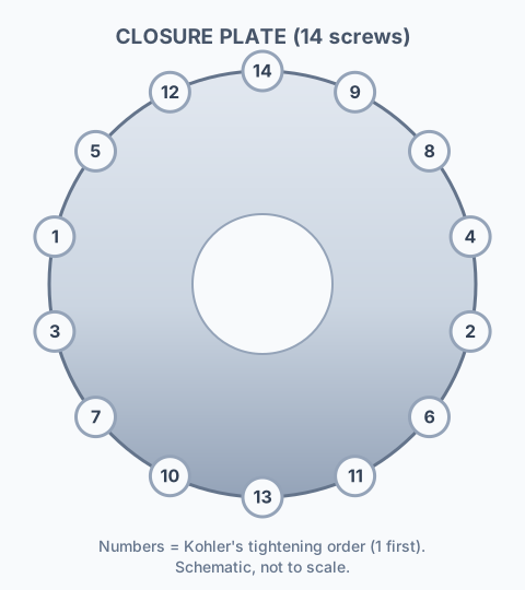
| closure plate fastener | 227 in-lb≈ 18.9 ft-lbHigh | 25.6 N·m (227 in. lb.). 14-position tightening sequence, diagrammed on p.74 (see the sequence diagram below). Why ›Called "Closure Plate Fastener" in this CH manual; the CV manual below calls the equivalent fastener the "Oil Pan Fastener" -- same fastener role, different manual, different name -- form 62 690 01 Rev. O, p.14. |
| connecting rod cap fastener (torque in increments) | 103 in-lb≈ 8.6 ft-lbHigh | 11.6 N·m (103 in. lb.) -- form 62 690 01 Rev. O, p.14. |
| control bracket mounting screw (into intake manifold from air cleaner) | 90 in-lb≈ 7.5 ft-lbHigh | 10.2 N·m (90 in. lb.) -- form 62 690 01 Rev. O, p.14. |
| control panel M6 screw, into NEW holesM6 | 100 in-lb≈ 8.3 ft-lbHigh | 11.3 N·m (100 in. lb.) -- form 62 690 01 Rev. O, p.15. |
| control panel M6 screw, into USED holesM6 | 69 in-lb≈ 5.8 ft-lbHigh | 7.7 N·m (69 in. lb.) -- form 62 690 01 Rev. O, p.15. |
| control panel M5 screws, into NEW holesM5 | 58 in-lb≈ 4.8 ft-lbHigh | 6.5 N·m (58 in. lb.) -- form 62 690 01 Rev. O, p.15. |
| control panel M5 screws, into USED holesM5 | 37 in-lb≈ 3.1 ft-lbHigh | 4.1 N·m (37 in. lb.) -- form 62 690 01 Rev. O, p.15. |
| crankcase breather cover fastener | 110 in-lb≈ 9.2 ft-lbHigh | 12.4 N·m (110 in. lb.) -- form 62 690 01 Rev. O, p.15. Why ›The companion CV manual carries the identical 12.4 N·m table figure but a 12.5 N·m reassembly-step figure -- see the CV engine below. |
| crankcase oil drain plug | 16 ft-lbHigh | 21.4 N·m (16 ft. lb.) -- form 62 690 01 Rev. O, p.15. |
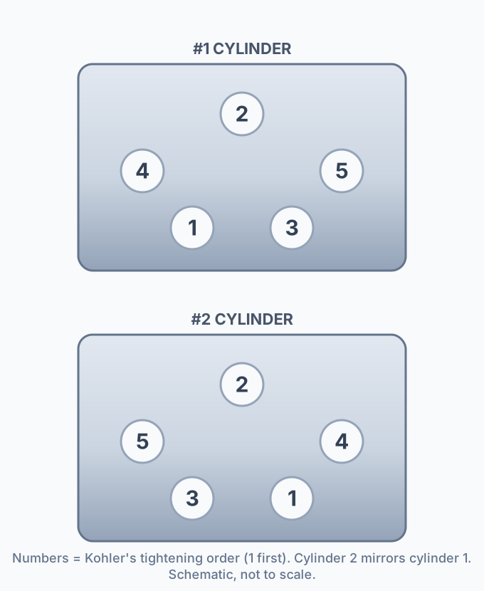
| cylinder head bolt (torque in 2 increments) | 415 in-lb≈ 34.6 ft-lbHigh | Torqued in 2 stages: final 415 in. lb. Why ›(46.9 N·m); initial 210 in. lb. (23.7 N·m). 5-bolt-per-head tightening sequence, diagrammed on p.77 (see the sequence diagram below) -- p.77 prints two pairs of head drawings (two head castings), both carrying the identical 1-5 numbering; cylinder 1 and cylinder 2 heads are mirror images, not two different sequences. 415 in-lb is not printed as a ft-lb figure by Kohler. Do NOT apply this figure to the smaller CH620-CH750 V-Twin (370 in-lb/41.8 N·m final) -- see /small-engines/kohler-engine-torque-specs/. form 62 690 01 Rev. O, p.15 table, p.77 procedure. |
| pipe plug, cylinder head (3/4 in.)3/4 in. pipe plug (as printed) | 252 in-lb= 21 ft-lbHigh | 28.5 N·m (252 in. lb.) -- form 62 690 01 Rev. O, p.15. |
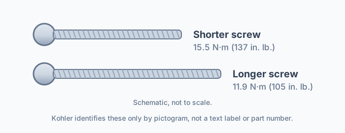
| rocker arm screw -- shorter screw (per Kohler’s pictogram) | 137 in-lb≈ 11.4 ft-lbHigh | 15.5 N·m (137 in. lb.) -- form 62 690 01 Rev. O, p.15. Why ›Kohler’s table identifies this row only by a screw pictogram, not a text label or part number -- the drawing shows a visibly shorter shank than the row below. See the rocker-arm-screw drawing below. Do not use the "black/silver" screw wording from the CH620-CH750 page -- that is a different engine family with different screws and different torques. |
| rocker arm screw -- longer screw (per Kohler’s pictogram) | 105 in-lb≈ 8.8 ft-lbHigh | 11.9 N·m (105 in. lb.) -- form 62 690 01 Rev. O, p.15. Why ›Kohler’s table identifies this row only by a screw pictogram, not a text label or part number -- the drawing shows a visibly longer shank than the row above. See the rocker-arm-screw drawing below. |
| debris screen fastener | 88 in-lb≈ 7.3 ft-lbHigh | 9.9 N·m (88 in. lb.) -- form 62 690 01 Rev. O, p.15. |
| debris screen hex stud | 190 in-lb≈ 15.8 ft-lbHigh | 21.5 N·m (190 in. lb.) -- form 62 690 01 Rev. O, p.15. |
| debris screen mounting screw, hex flange screw | 180 in-lb= 15 ft-lbHigh | 20.3 N·m (180 in. lb.) -- form 62 690 01 Rev. O, p.15. |
| debris screen mounting screw, button head cap screw | 88 in-lb≈ 7.3 ft-lbHigh | 9.9 N·m (88 in. lb.) -- form 62 690 01 Rev. O, p.15. |
| front drive shaft screw (into flywheel) | 216 in-lb= 18 ft-lbHigh | 24.4 N·m (216 in. lb.). CH-only fastener, for the front-PTO option -- form 62 690 01 Rev. O, p.15. |
| fan fastener screw, truss head | 92 in-lb≈ 7.7 ft-lbHigh | 10.4 N·m (92 in. lb.) -- form 62 690 01 Rev. O, p.15. |
| fan fastener screw, hex head | 88 in-lb≈ 7.3 ft-lbHigh | 9.9 N·m (88 in. lb.) -- form 62 690 01 Rev. O, p.15. |
| flywheel retaining screw | 51 ft-lbHigh | 69.8 N·m (51 ft. lb.). This platform uses a screw with a washer, not a flywheel nut -- form 62 690 01 Rev. O, p.15, install steps p.81. |
| governor lever nut | 63 in-lb≈ 5.3 ft-lbHigh | 7.1 N·m (63 in. lb.) -- form 62 690 01 Rev. O, p.15. |
| governor yoke mounting screw | 20 in-lb≈ 1.7 ft-lbHigh | 2.2 N·m (20 in. lb.) -- form 62 690 01 Rev. O, p.15. |
| spark plug | 20 ft-lbHigh | 27 N·m (20 ft. lb.). Gap 0.76 mm (0.030 in.) -- form 62 690 01 Rev. O, p.15. |
| ignition module fastener, into NEW holes | 86 in-lb≈ 7.2 ft-lbHigh | 9.7 N·m (86 in. lb.) -- form 62 690 01 Rev. O, p.15. |
| ignition module fastener, into USED holes | 37 in-lb≈ 3.1 ft-lbHigh | 4.1 N·m (37 in. lb.) -- form 62 690 01 Rev. O, p.15. |
| rectifier-regulator fastener | 22 in-lb≈ 1.8 ft-lbHigh | 2.5 N·m (22 in. lb.) -- form 62 690 01 Rev. O, p.15. |
| lifter feed chamber cover/baffle screw | 68 in-lb≈ 5.7 ft-lbHigh | 7.7 N·m (68 in. lb.) -- form 62 690 01 Rev. O, p.15. |
| muffler retaining nut | 216 in-lb= 18 ft-lbHigh | 24.4 N·m (216 in. lb.) -- form 62 690 01 Rev. O, p.15. |
| muffler M6 screwM6 | 88 in-lb≈ 7.3 ft-lbHigh | 9.9 N·m (88 in. lb.) -- form 62 690 01 Rev. O, p.15. |
| muffler M8 screwM8 | 216 in-lb= 18 ft-lbHigh | 24.4 N·m (216 in. lb.) -- form 62 690 01 Rev. O, p.15. |
| oil cooler mounting screws | 21 in-lb≈ 1.8 ft-lbHigh | 2.3 N·m (21 in. lb.) -- form 62 690 01 Rev. O, p.16. |
| oil filter adapter/housing mounting screwM8 (per p.79 body text) | 210 in-lb≈ 17.5 ft-lbHigh | 23.7 N·m (210 in. lb.) -- form 62 690 01 Rev. O, p.16. |
| oil filter nipple | 158 in-lb≈ 13.2 ft-lbHigh | 17.8 N·m (158 in. lb.) -- form 62 690 01 Rev. O, p.16. |
| oil pickup screen mounting screw, into NEW holes | 82 in-lb≈ 6.8 ft-lbHigh | 9.3 N·m (82 in. lb.) -- form 62 690 01 Rev. O, p.16. Why ›This is a different fastener and a different figure from the "oil pickup tube" screw below, even though both are near identical in name. |
| oil pickup screen mounting screw, into USED holes | 68 in-lb≈ 5.7 ft-lbHigh | 7.7 N·m (68 in. lb.) -- form 62 690 01 Rev. O, p.16. |
| oil pickup tube mounting screw, into NEW holes | 100 in-lb≈ 8.3 ft-lbHigh | 11.3 N·m (100 in. lb.) -- form 62 690 01 Rev. O, p.16. Why ›The CV manual’s "oil pickup screen" screw uses this same 11.3 N·m figure under a different name -- see the CV engine below. |
| oil pickup tube mounting screw, into USED holes | 68 in-lb≈ 5.7 ft-lbHigh | 7.7 N·m (68 in. lb.) -- form 62 690 01 Rev. O, p.16. |
| oil pump mounting screw | 88 in-lb≈ 7.3 ft-lbHigh | 9.9 N·m (88 in. lb.) -- form 62 690 01 Rev. O, p.16. |
| Oil Sentry pressure switch | 95 in-lb≈ 7.9 ft-lbHigh | 10.7 N·m (95 in. lb.) -- form 62 690 01 Rev. O, p.16. |
| oil reservoir mounting screw | 227 in-lb≈ 18.9 ft-lbHigh | 25.6 N·m (227 in. lb.) -- form 62 690 01 Rev. O, p.16. Why ›8-position sequence printed on p.74 of the manual (not reproduced here); it is a different part and a different pattern from the 14-screw closure plate above. |
| starter solenoid mounting hardware | 35–53 in-lbHigh | 4.0-6.0 N·m (35-53 in. lb.) -- form 62 690 01 Rev. O, p.16. |
| starter solenoid nut, positive (+) brush lead | 71–97 in-lbHigh | 8.0-11.0 N·m (71-97 in. lb.) -- form 62 690 01 Rev. O, p.16. |
| starter assembly thru bolt | 49–79 in-lbHigh | 5.6-9.0 N·m (49-79 in. lb.) -- form 62 690 01 Rev. O, p.16. |
| starter assembly mounting screw | 142 in-lb≈ 11.8 ft-lbHigh | 16.0 N·m (142 in. lb.) -- form 62 690 01 Rev. O, p.16. |
| starter assembly brush holder mounting screw | 22–29 in-lbHigh | 2.5-3.3 N·m (22-29 in. lb.) -- form 62 690 01 Rev. O, p.16. |
| stator mounting screw | 82 in-lb≈ 6.8 ft-lbHigh | 9.3 N·m (82 in. lb.) -- form 62 690 01 Rev. O, p.16. |
| throttle/choke control bracket fastener | 90 in-lb≈ 7.5 ft-lbHigh | 10.2 N·m (90 in. lb.) -- form 62 690 01 Rev. O, p.16. |
| valve cover fastener (aluminum cover, into a NEW head) | 160 in-lb≈ 13.3 ft-lbHigh | Torqued in 3 steps, final 160 in. lb. Why ›(18.1 N·m): first seat the seal by torquing to 230 in. lb. (26 N·m), then back the screw off to zero, then torque again to the final 160 in. lb. (18.1 N·m) -- form 62 690 01 Rev. O, p.16. |
| valve cover fastener (aluminum cover, into a USED head) | 145 in-lb≈ 12.1 ft-lbHigh | Three-step procedure: Step 1, torque to 145 in. lb. Why ›(16.4 N·m) to seat the seal in the valve cover groove; Step 2, back the screw off to zero; Step 3 (final), torque again to 145 in. lb. (16.4 N·m) -- form 62 690 01 Rev. O, p.16. |
| valve cover fastener (plastic cover) | 120 in-lb= 10 ft-lbHigh | 13.6 N·m (120 in. lb.) -- form 62 690 01 Rev. O, p.16. |
2 specs not published — oil filter (spin-on cartridge), blade / PTO / clutch / deck fasteners What we found ›
- oil filter (spin-on cartridge)GAP: no numeric torque. Kohler says only to pre-fill and oil the gasket, then "refer to instructions on oil filter for proper installation" -- form 62 690 01 Rev. O, p.87.
- blade / PTO / clutch / deck fastenersGAP: not in this manual. Kohler defers entirely: "Refer to operating instruction of equipment that this engine powers" (p.1). This is an engine-only service manual -- blade, PTO, deck and pump fasteners belong to the equipment manufacturer’s own manual (Scag, Exmark, Hustler, Bad Boy, etc.).
Kohler Command PRO CV940-CV1000 (vertical shaft)999cc Manufacturer-published
series CV940, CV960, CV980, CV1000Covers Kohler service manual form 62 690 02 Rev. N (2022), carbureted engines only -- the ECV940-ECV980 EFI variants are not covered by this… More about this engine ›
manual or this page. Transcribed independently from the CH manual above -- every value here comes from the CV manual's own printed table, never copied across from CH.
| Fastener | Torque | Where it comes from |
|---|---|---|
| blower housing / sheet metal M6 screw, new untapped hole (casting)M6 | 95 in-lb≈ 7.9 ft-lbHigh | 10.7 N·m (95 in. lb.) -- form 62 690 02 Rev. N, p.6. |
| blower housing / sheet metal M6 screw, used tapped hole (casting)M6 | 65 in-lb≈ 5.4 ft-lbHigh | 7.3 N·m (65 in. lb.) -- form 62 690 02 Rev. N, p.6. |
| blower housing / sheet metal M6 screw, new extruded hole (sheet metal)M6 | 22 in-lb≈ 1.8 ft-lbHigh | 2.5 N·m (22 in. lb.) -- form 62 690 02 Rev. N, p.6. |
| blower housing / sheet metal M6 screw, used extruded hole (sheet metal)M6 | 18 in-lb≈ 1.5 ft-lbHigh | 2.0 N·m (18 in. lb.) -- form 62 690 02 Rev. N, p.6. |
| blower housing / sheet metal M6 screw, mounting clip (valley baffle)M6 | 22 in-lb≈ 1.8 ft-lbHigh | 2.5 N·m (22 in. lb.) -- form 62 690 02 Rev. N, p.6. |
| intake manifold mounting fastener (torque in 2 increments) | 200 in-lb≈ 16.7 ft-lbHigh | Torqued in 2 stages: final 200 in. lb. Why ›(22.6 N·m); initial 150 in. lb. (16.9 N·m). Sequence printed on p.64 of the manual (not reproduced here) -- form 62 690 02 Rev. N, p.6. |
| carburetor / air cleaner mounting nut | 100 in-lb≈ 8.3 ft-lbHigh | 11.3 N·m (100 in. lb.) -- form 62 690 02 Rev. N, p.6. |
| air cleaner mounting screw (into intake manifold) | 100 in-lb≈ 8.3 ft-lbHigh | 11.3 N·m (100 in. lb.) -- form 62 690 02 Rev. N, p.6. |
| carburetor fuel bowl screw | 22 in-lb≈ 1.8 ft-lbHigh | 2.5 N·m ± 0.3 (22 in. lb. ± 2.3 in. lb.) -- form 62 690 02 Rev. N, p.6. Why ›The CH manual states the same 2.5 N·m ± 0.3 but rounds its English tolerance to "3 in. lb." instead; same metric spec, different printed English rounding. |
| connecting rod cap fastener (torque in increments) | 103 in-lb≈ 8.6 ft-lbHigh | 11.6 N·m (103 in. lb.) -- form 62 690 02 Rev. N, p.6. |
| control bracket mounting screw (into intake manifold from air cleaner) | 90 in-lb≈ 7.5 ft-lbHigh | 10.2 N·m (90 in. lb.) -- form 62 690 02 Rev. N, p.6. |
| crankcase breather cover fastener | 110 in-lb≈ 9.2 ft-lbHigh⚠ sources disagree | 12.4 N·m (110 in. lb.), per the torque table (form 62 690 02 Rev. N, p.6). Why ›CONFLICT: the same manual’s Reassembly procedure (p.60) instead says "install screws and torque to 12.5 N·m (110 in. lb.) following sequence." Both are printed by Kohler for the identical English figure (110 in. lb.) -- shown here as the table’s 12.4 N·m with the procedure’s 12.5 N·m footnoted. The companion CH manual is internally consistent at 12.4 N·m in both places. |
| crankcase oil drain plug | 16 ft-lbHigh | 21.4 N·m (16 ft. lb.) -- form 62 690 02 Rev. N, p.6. |
| crankcase dipstick tube screw | 68 in-lb≈ 5.7 ft-lbHigh | 7.7 N·m (68 in. lb.). CV-only fastener -- not a table row in the CH manual. form 62 690 02 Rev. N, p.6. |
| cylinder head bolt (torque in 2 increments) | 415 in-lb≈ 34.6 ft-lbHigh | Torqued in 2 stages: final 415 in. lb. Why ›(46.9 N·m); initial 210 in. lb. (23.7 N·m). 5-bolt-per-head tightening sequence, diagrammed on p.62 (see the sequence diagram below), identical figures and sequence to the companion CH manual. 415 in-lb is not printed as a ft-lb figure by Kohler. Do NOT apply this figure to the smaller CV620-CV750 V-Twin (370 in-lb/41.8 N·m final) -- see /small-engines/kohler-engine-torque-specs/. form 62 690 02 Rev. N, p.7 table, p.62 procedure. |
| pipe plug, cylinder head (3/4 in.)3/4 in. pipe plug (as printed) | 252 in-lb= 21 ft-lbHigh | 28.5 N·m (252 in. lb.) -- form 62 690 02 Rev. N, p.7. |
| rocker arm stud (AVT -- adjustable valve train) | 100 in-lb≈ 8.3 ft-lbHigh | 11.3 N·m (100 in. lb.). CV-only fastener -- the CH manual has no AVT variant. form 62 690 02 Rev. N, p.7. |
| setscrew, AVT pivot locking | 69 in-lb≈ 5.8 ft-lbHigh | 7.7 N·m (69 in. lb.). CV-only fastener. form 62 690 02 Rev. N, p.7. |
| rocker arm screw (Non-AVT) -- shorter screw (per Kohler’s pictogram) | 137 in-lb≈ 11.4 ft-lbHigh | 15.5 N·m (137 in. lb.) -- form 62 690 02 Rev. N, p.7. Why ›Kohler’s table identifies this row only by a screw pictogram, not a text label or part number -- the drawing shows a visibly shorter shank than the row below. See the rocker-arm-screw drawing below. Do not use the "black/silver" screw wording from the CH620-CH750/CV620-CV750 page -- that is a different engine family with different screws and different torques. |
| rocker arm screw (Non-AVT) -- longer screw (per Kohler’s pictogram) | 105 in-lb≈ 8.8 ft-lbHigh | 11.9 N·m (105 in. lb.) -- form 62 690 02 Rev. N, p.7. Why ›Kohler’s table identifies this row only by a screw pictogram, not a text label or part number -- the drawing shows a visibly longer shank than the row above. See the rocker-arm-screw drawing below. |
| debris screen hex stud | 190 in-lb≈ 15.8 ft-lbHigh | 21.5 N·m (190 in. lb.) -- form 62 690 02 Rev. N, p.7. |
| debris screen mounting screw, hex flange screw | 180 in-lb= 15 ft-lbHigh | 20.3 N·m (180 in. lb.) -- form 62 690 02 Rev. N, p.7. |
| debris screen mounting screw, button head cap screw | 88 in-lb≈ 7.3 ft-lbHigh | 9.9 N·m (88 in. lb.) -- form 62 690 02 Rev. N, p.7. |
| fan fastener | 92 in-lb≈ 7.7 ft-lbHigh | 10.4 N·m (92 in. lb.) -- form 62 690 02 Rev. N, p.7. Why ›The CV manual publishes one fan-fastener figure; the CH manual splits this into separate truss-head and hex-head rows -- see the CH engine above. |
| flywheel retaining screw | 51 ft-lbHigh | 69.8 N·m (51 ft. lb.). This platform uses a screw with a washer, not a flywheel nut -- form 62 690 02 Rev. N, p.7, install steps p.66. |
| fuel pump screw | 70 in-lb≈ 5.8 ft-lbHigh | 7.9 N·m (70 in. lb.) -- form 62 690 02 Rev. N, p.7. Why ›CV-only fastener -- the CH manual describes an optional remote electric fuel pump but prints no fuel-pump-screw torque of its own. Do not carry this figure onto a CH engine. |
| governor lever nut | 63 in-lb≈ 5.3 ft-lbHigh | 7.1 N·m (63 in. lb.) -- form 62 690 02 Rev. N, p.7. |
| governor yoke mounting screw | 20 in-lb≈ 1.7 ft-lbHigh | 2.2 N·m (20 in. lb.) -- form 62 690 02 Rev. N, p.7. |
| spark plug | 20 ft-lbHigh | 27 N·m (20 ft. lb.). Gap 0.76 mm (0.030 in.) -- form 62 690 02 Rev. N, p.7. |
| ignition module fastener, into NEW holes | 86 in-lb≈ 7.2 ft-lbHigh | 9.7 N·m (86 in. lb.) -- form 62 690 02 Rev. N, p.7. |
| ignition module fastener, into USED holes | 37 in-lb≈ 3.1 ft-lbHigh | 4.1 N·m (37 in. lb.) -- form 62 690 02 Rev. N, p.7. |
| rectifier-regulator fastener | 22 in-lb≈ 1.8 ft-lbHigh | 2.5 N·m (22 in. lb.) -- form 62 690 02 Rev. N, p.7. |
| lifter feed chamber cover screw | 68 in-lb≈ 5.7 ft-lbHigh | 7.7 N·m (68 in. lb.) -- form 62 690 02 Rev. N, p.7. |
| muffler retaining nut | 216 in-lb= 18 ft-lbHigh | 24.4 N·m (216 in. lb.) -- form 62 690 02 Rev. N, p.7. |
| muffler screw, intermittent bracket (into weld nut) | 120 in-lb= 10 ft-lbHigh | 13.6 N·m (120 in. lb.). CV-only fastener -- not a table row in the CH manual. form 62 690 02 Rev. N, p.7. |
| muffler M6 screwM6 | 88 in-lb≈ 7.3 ft-lbHigh | 9.9 N·m (88 in. lb.) -- form 62 690 02 Rev. N, p.7. |
| muffler M8 screwM8 | 216 in-lb= 18 ft-lbHigh | 24.4 N·m (216 in. lb.) -- form 62 690 02 Rev. N, p.7. |
| oil cooler mounting screw | 21 in-lb≈ 1.8 ft-lbHigh | 2.3 N·m (21 in. lb.) -- form 62 690 02 Rev. N, p.7. |
| oil filter adapter/housing mounting screwM8 (per p.64 body text) | 210 in-lb≈ 17.5 ft-lbHigh | 23.7 N·m (210 in. lb.) -- form 62 690 02 Rev. N, p.7. |
| oil filter nipple | 158 in-lb≈ 13.2 ft-lbHigh | 17.8 N·m (158 in. lb.) -- form 62 690 02 Rev. N, p.7. |
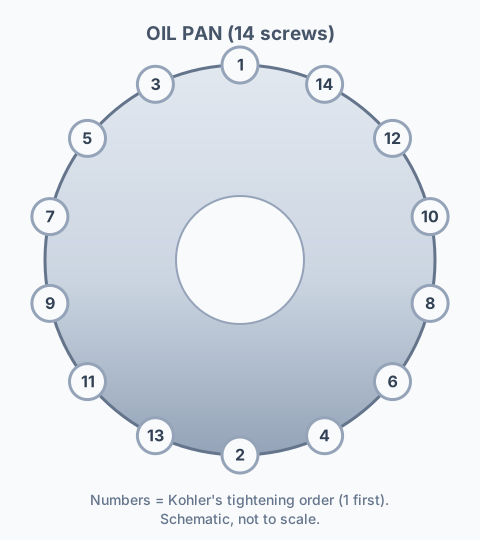
| oil pan fastener (crankcase closure) | 227 in-lb≈ 18.9 ft-lbHigh | 25.6 N·m (227 in. lb.). 14-position tightening sequence, diagrammed on p.60 (see the sequence diagram below). Why ›Called "Oil Pan Fastener" in this CV manual; the CH manual above calls the equivalent fastener the "Closure Plate Fastener" -- same fastener role, different manual, different name. form 62 690 02 Rev. N, p.7. |
| oil pickup screen mounting screw, into a NEW hole | 100 in-lb≈ 8.3 ft-lbHigh | 11.3 N·m (100 in. lb.) -- form 62 690 02 Rev. N, p.8. Why ›The CH manual’s "oil pickup screen" screw (a different, lower figure -- 9.3 N·m) is a genuinely different printed value for a similarly-named fastener; in CH, 11.3 N·m is instead the separate "oil pickup tube" screw. Do not assume these two manuals share this figure. |
| oil pickup screen mounting screw, into a USED hole | 68 in-lb≈ 5.7 ft-lbHigh | 7.7 N·m (68 in. lb.) -- form 62 690 02 Rev. N, p.8. |
| oil pump mounting screw | 88 in-lb≈ 7.3 ft-lbHigh | 9.9 N·m (88 in. lb.) -- form 62 690 02 Rev. N, p.8. |
| Oil Sentry pressure switch | 95 in-lb≈ 7.9 ft-lbHigh | 10.7 N·m (95 in. lb.) -- form 62 690 02 Rev. N, p.8. |
| starter solenoid mounting hardware | 35–53 in-lbHigh | 4.0-6.0 N·m (35-53 in. lb.) -- form 62 690 02 Rev. N, p.8. |
| starter solenoid nut, positive (+) brush lead | 71–97 in-lbHigh | 8.0-11.0 N·m (71-97 in. lb.) -- form 62 690 02 Rev. N, p.8. |
| starter assembly thru bolt | 49–79 in-lbHigh | 5.6-9.0 N·m (49-79 in. lb.) -- form 62 690 02 Rev. N, p.8. |
| starter assembly mounting screw | 142 in-lb≈ 11.8 ft-lbHigh | 16.0 N·m (142 in. lb.) -- form 62 690 02 Rev. N, p.8. |
| starter assembly brush holder mounting screw | 22–29 in-lbHigh | 2.5-3.3 N·m (22-29 in. lb.) -- form 62 690 02 Rev. N, p.8. |
| stator mounting screw | 82 in-lb≈ 6.8 ft-lbHigh | 9.3 N·m (82 in. lb.) -- form 62 690 02 Rev. N, p.8. |
| throttle/choke control bracket fastener | 90 in-lb≈ 7.5 ft-lbHigh | 10.2 N·m (90 in. lb.) -- form 62 690 02 Rev. N, p.8. |
| valve cover fastener (aluminum cover, into a NEW head) | 160 in-lb≈ 13.3 ft-lbHigh | Torqued in 3 steps, final 160 in. lb. Why ›(18.1 N·m): first seat the seal by torquing to 230 in. lb. (26 N·m), then back the screw off to zero, then torque again to the final 160 in. lb. (18.1 N·m) -- form 62 690 02 Rev. N, p.8. |
| valve cover fastener (aluminum cover, into a USED head) | 145 in-lb≈ 12.1 ft-lbHigh | Three-step procedure: Step 1, torque to 145 in. lb. Why ›(16.4 N·m) to seat the seal in the valve cover groove; Step 2, back the screw off to zero; Step 3 (final), torque again to 145 in. lb. (16.4 N·m) -- form 62 690 02 Rev. N, p.8. |
| valve cover fastener (plastic cover) | 120 in-lb= 10 ft-lbHigh | 13.6 N·m (120 in. lb.) -- form 62 690 02 Rev. N, p.8. |
2 specs not published — oil filter (spin-on cartridge), blade / PTO / clutch / deck fasteners What we found ›
- oil filter (spin-on cartridge)GAP: no numeric torque. Kohler says only to pre-fill and oil the gasket, then "refer to instructions on oil filter for proper installation" -- form 62 690 02 Rev. N, p.70.
- blade / PTO / clutch / deck fastenersGAP: not in this manual. Kohler defers entirely: "Refer to operating instruction of equipment that this engine powers" (p.1). This is an engine-only service manual -- blade, PTO, deck and pump fasteners belong to the equipment manufacturer’s own manual (Scag, Exmark, Hustler, Bad Boy, etc.).
Kohler Command PRO 999cc tightening SEQUENCES and rocker-screw pictogram
The head bolts and the closure plate/oil pan screws are multi-bolt patterns Kohler tightens in a specific numbered order, printed only as a diagram. The rocker arm screw row is printed as two unlabeled screw pictograms rather than a text description. The diagrams below are redrawn from Kohler's own CH and CV service manuals -- the numbers are Kohler's tightening order, not a pixel trace of the manual's artwork.
Cylinder head bolt sequence (5 bolts per head) -- identical on CH and CV
Both manuals print the same 1-5 numbering: bolts 1 and 3 sit near the bottom, bolt 2 sits at top-center, and bolts 4 and 5 sit on the outer sides. Cylinder 2 is a mirror image of cylinder 1, not a different sequence. Torque in that 1-2-3-4-5 order, in the two increments from the table above (23.7 N·m/210 in-lb first, 46.9 N·m/415 in-lb final). The CH manual additionally prints two identical head-drawing pairs (one per head casting) with this same numbering.
CH closure plate sequence (14 screws)
The crankcase closure plate uses 14 screws, numbered 1 through 14 in Kohler's diagram, arranged around the plate perimeter (10 at bottom-left, 13 at bottom-centre, 11 at bottom-right). Torque in that numbered order to 25.6 N·m (227 in-lb).
CV oil pan sequence (14 screws)
The CV oil pan (the vertical-shaft equivalent of the CH closure plate above) uses the same 14-screw count, numbered 1 through 14 around the pan perimeter with a single screw (2) at the bottom center. Torque in that numbered order to 25.6 N·m (227 in-lb).
Rocker arm screw pictogram -- which one is "shorter" and which is "longer"
Neither manual gives the rocker arm screw row a text label, part number or length -- only two screw pictograms, stacked one above the other. The upper pictogram draws a visibly shorter shank and torques to 15.5 N·m (137 in-lb); the lower pictogram draws a visibly longer shank and torques to 11.9 N·m (105 in-lb). The pictogram below is identical between CH and CV except for the CV row's "(Non-AVT)" label -- CV also has separate AVT rocker stud/setscrew rows the CH manual does not (see the CV table above).
What is the head bolt torque on a Kohler Command PRO 999cc (CH940-CH1000 / CV940-CV1000)?
Both the CH and CV manuals specify the identical two-step figure: 23.7 N·m (210 in-lb) first, then a final pass to 46.9 N·m (415 in-lb), following the 5-bolt-per-head sequence (p.77 CH, p.62 CV). Do not use the smaller CH620-CH750/CV620-CV750 V-Twin's figure (41.8 N·m/370 in-lb) on this engine -- it's a different, lower spec.
What's the flywheel screw torque on the Kohler 999cc Command PRO?
69.8 N·m (51 ft-lb), identical in both the CH and CV manuals -- a flywheel retaining screw with a washer, not a nut. The Command CH/CV V-Twins (620-750 at 66.4 N·m / 49 ft-lb, and 940-1000) all use a screw; the XT and the CH395/CH440 singles use a nut.
Are the CH940-CH1000 and CV940-CV1000 torque specs interchangeable with the smaller CH620-CH750/CV620-CV750 V-Twin?
No. Nearly every shared fastener runs higher on the 999cc engine -- head bolt final 46.9 N·m (415 in-lb) vs 41.8 N·m (370 in-lb), flywheel screw 69.8 N·m (51 ft-lb) vs 66.4 N·m (49 ft-lb), oil drain plug 21.4 N·m (16 ft-lb) vs 13.6 N·m (10 ft-lb), closure plate/oil pan 25.6 N·m (227 in-lb) vs 24.4 N·m (216 in-lb). See /small-engines/kohler-engine-torque-specs/ for the smaller V-Twin's own figures.
Which rocker arm screw is which on the 999cc Command PRO -- the manual just shows pictures?
Kohler's own table gives no text label, only two screw pictograms. The visibly shorter screw (upper pictogram) torques to 15.5 N·m (137 in-lb); the visibly longer screw (lower pictogram) torques to 11.9 N·m (105 in-lb) -- see the pictogram drawing above. This is a different pair of screws and different torques from the "black/silver" M6 screws on the smaller CH620-CH750/CV620-CV750 page.
Does this page cover the EFI version of the Command PRO 999cc?
No. Both manuals used here (form 62 690 01 and 62 690 02) cover the carbureted CH940-CH1000/CV940-CV1000 only -- "EFI" appears only in a tool-kit listing, and no service manual could be found for the ECH/ECV 940-980 EFI variants (the expected document numbers return 404 at Kohler's own site). Do not apply these figures to an EFI engine without confirming them against its own manual.
Related lookups
- Honda GX Series Engine Torque Specs
- Briggs & Stratton Engine Torque Specs
- Predator (Harbor Freight) Engine Torque Specs
- Kohler Engine Torque Specs
- Kohler K-Series & Magnum Engine Torque Specs
- Kohler XT Engine Torque Specs
- Kawasaki Engine Torque Specs
- Honda GCV Series Engine Torque Specs
- Stihl Engine Torque Specs
- Husqvarna Chainsaw Torque Specs
- Echo Engine Torque Specs
- Tecumseh Engine Torque Specs
- Onan Engine Torque Specs
- LCT Engine Torque Specs
- Carburetor, Muffler & Blower Housing Specs
- Snow Blower Shear Pin Sizes
- All Small Engine Specs
- Wrench & Socket Size Finder
Loading interactive lookup…