Kohler XT Engine Torque Specs
Cylinder head bolt torque at a glance
HighMediumLow= how many independent sources agree
The in-lb/ft-lb figure on this page is Kohler's own printed number, not a conversion. Kohler prints N·m first, then the inch- or foot-pound equivalent in parentheses; the N·m figure is quoted in each row's note. The flywheel nut and spark plug are the only two rows Kohler prints in foot-pounds; every other row on this page is inch-pounds.
The Kohler XT is the single-cylinder vertical-shaft engine on most Kohler-powered push mowers -- badged XT-6, XTR-6, XT6.5, XT650, XT6.75 and XT675 on the 149cc block, or XT-7, XTR-7, XT775 and XT8 on the 173cc block. Every figure below is transcribed from Kohler's own XT service… Read the rest ›
manual exactly as printed. Kohler prints N·m first with the inch- or foot-pound figure in parentheses; the in-lb/ft-lb shown here is Kohler's own printed figure, not a conversion. Kohler's XT manual does NOT publish a blade bolt, blade adapter or PTO fastener torque; if you came here for that figure, see the note below and check your mower's own manual instead.
Where these numbers come from. 36 published figures, 2 confirmed gaps, every source named. How we checked ›
Every value on this page comes from Kohler's "XT-6, XTR-6, XT6.5, XT650, XT6.75, XT675, XT-7, XTR-7, XT775, XT8 Service Manual," form 14 690 01 Rev. G (PDF created 2014-12-16, hosted directly at resources.kohler.com). The manual prints its Torque Specifications table across p.5-6 as ONE shared column for all ten model names -- only the oil pan screw differs between the two bore families, and that split is shown as two separate rows below. A handful of additional fastener torques appear only in the manual's reassembly procedure text (pp.25, 32, 50, 51, 54, 55), not in the summary table -- those are cited to their own page, including a fuel-tank top-mount stud figure (p.51) that is not in the main torque table at all. One real internal disagreement surfaced: the governor lever fastener is 9.5 N·m (84 in-lb) in the torque table but 10 N·m (88.5 in-lb) in the Initial Governor Adjustment procedure a few pages later -- both are printed by Kohler and both are shown, not silently picked. Rev. G is the only revision hosted at Kohler's canonical URL; no later revision was found. The manual's own model-decode page (p.5) gives serial year codes 42-44 for 2012-2014, but prints no serial break-point for any torque value -- these figures apply across the whole XT-6/XT-7 production run as far as the manual documents. Kohler's XT manual does not publish a blade bolt, blade adapter or PTO fastener torque, and has no oil filter at all -- both are recorded as confirmed gaps below rather than left unmentioned.
Kohler XT-6 / XT-7 (all models) Manufacturer-published
series XT-6, XTR-6, XT6.5, XT650, XT6.75, XT675 (149cc, 65mm bore) and XT-7, XTR-7, XT775, XT8 (173cc, 70mm bore) -- shared 45mm strokeCovers Kohler service manual form 14 690 01 Rev. G (2015). More about this engine ›
Kohler prints one shared torque table for all ten model names in this manual -- only the oil pan screw differs by bore family, shown as two separate rows below. Every other row applies to the whole XT-6/XT-7 line.
| Fastener | Torque | Where it comes from |
|---|---|---|
| air cleaner base stud fastener | 71 in-lb≈ 5.9 ft-lbHigh | 8 N·m (71 in. lb.) -- form 14 690 01 Rev. G, p.5. |
| air cleaner base crankcase fastener | 71 in-lb≈ 5.9 ft-lbHigh | 8 N·m (71 in. lb.). A separate table row from the stud fastener above, same figure -- form 14 690 01 Rev. G, p.5. |
| blower housing stud | 88 in-lb≈ 7.3 ft-lbHigh | 10 N·m (88 in. lb.) -- form 14 690 01 Rev. G, p.5. |
| blower housing nut | 70 in-lb≈ 5.8 ft-lbHigh | 8 N·m (70 in. lb.) -- form 14 690 01 Rev. G, p.5. Why ›Printed as "70 in. lb." here even though every other 8 N·m row on this page reads "71 in. lb."; reproduced as Kohler printed it, not corrected. |
| flywheel brake mounting fastener | 84 in-lb= 7 ft-lbHigh | 9.5 N·m (84 in. lb.) -- form 14 690 01 Rev. G, p.5. |
| breather cover fastener | 88 in-lb≈ 7.3 ft-lbHigh | 10 N·m (88 in. lb.) -- form 14 690 01 Rev. G, p.5. |
| carburetor stud fastener | 71 in-lb≈ 5.9 ft-lbHigh | 8 N·m (71 in. lb.) -- form 14 690 01 Rev. G, p.5. |
| connecting rod cap fastener (torque in increments) | 110 in-lb≈ 9.2 ft-lbHigh | 12.5 N·m (110 in. lb.) -- form 14 690 01 Rev. G, p.6. |
| oil drain plug | 120 in-lb= 10 ft-lbHigh | 13.6 N·m (120 in. lb.). Footnote 7 lists the approved thread sealants for this plug and calls for sealant on 3 threads -- form 14 690 01 Rev. G, p.6. |
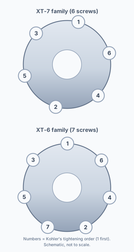
| oil pan screw (XT-6, XTR-6, XT6.5, XT6.75, XT650, XT675) | 98 in-lb≈ 8.2 ft-lbHigh | 11.0 N·m (98 in. lb.). 7-position tightening sequence, diagrammed on p.46 (see the sequence diagram below) -- form 14 690 01 Rev. G, p.6. Why ›The XT-7 family below uses a different screw count and a different torque. |
| oil pan screw (XT-7, XTR-7, XT775, XT8) | 130 in-lb≈ 10.8 ft-lbHigh | 14.7 N·m (130 in. lb.). 6-position tightening sequence, diagrammed on p.46 (see the sequence diagram below) -- form 14 690 01 Rev. G, p.6. |
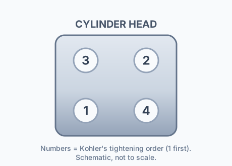
| cylinder head fastener (torque in 2 increments) | 246 in-lb≈ 20.5 ft-lbHigh | Torqued in 2 stages: final 246 in. lb. Why ›(27.8 N·m); initial 123 in. lb. (14 N·m). 4-bolt tightening sequence, diagrammed on p.49 (see the sequence diagram below). 246 in-lb is not printed as a ft-lb figure by Kohler -- form 14 690 01 Rev. G, p.6 table, p.49 procedure. |
| flywheel retaining nut | 38 ft-lbHigh | 51.5 N·m (38 ft. lb.). Use a strap wrench, not an impact gun -- form 14 690 01 Rev. G, p.6, install steps p.51. |
| fuel tank bracket-to-crankcase stud | 71 in-lb≈ 5.9 ft-lbHigh | 8 N·m (71 in. lb.) -- form 14 690 01 Rev. G, p.6. |
| fuel tank bracket-to-tank fastener | 40 in-lb≈ 3.3 ft-lbHigh | 4.5 N·m (40 in. lb.) -- form 14 690 01 Rev. G, p.6. |
| fuel tank top-mount threaded studs (to crankcase) | 88 in-lb≈ 7.3 ft-lbHigh | 10 N·m (88 in. lb.) -- form 14 690 01 Rev. G, p.51. Why ›Reassembly step 2 of "Install Fuel Tank," a different fastener from the bracket-to-crankcase stud above (that one is table-listed; this one is reassembly-procedure-only). |
| governor lever fastener | 84 in-lb= 7 ft-lbHigh⚠ sources disagree | 9.5 N·m (84 in. lb.), per the Torque Specifications table (form 14 690 01 Rev. G, p.6). Why ›CONFLICT: the same manual's Initial Governor Adjustment procedure (p.25) instead says "torque governor lever bolt to 10 N·m (88.5 in. lb.)." Both are printed by Kohler; this table figure is shown as the primary value and the procedure's 88.5 in. lb. (10 N·m) is the footnoted alternative. |
| governor gear fastener | 84 in-lb= 7 ft-lbHigh | 9.5 N·m (84 in. lb.) -- form 14 690 01 Rev. G, p.6. |
| spark plug | 20 ft-lbHigh | 27 N·m (20 ft. lb.) -- form 14 690 01 Rev. G, p.6. |
| ignition module fastener | 88 in-lb≈ 7.3 ft-lbHigh | 10 N·m (88 in. lb.) -- form 14 690 01 Rev. G, p.6. |
| ignition system screw | 88 in-lb≈ 7.3 ft-lbHigh | 10 N·m (88 in. lb.). Printed as its own table row, separate from the module fastener above, at the identical figure -- form 14 690 01 Rev. G, p.6. |
| muffler exhaust stud | 44 in-lb≈ 3.7 ft-lbHigh | 5.0 N·m (44 in. lb.) -- form 14 690 01 Rev. G, p.6. |
| muffler exhaust stud nut fastener | 84 in-lb= 7 ft-lbHigh | 9.5 N·m (84 in. lb.) -- form 14 690 01 Rev. G, p.6. |
| retractable (recoil) starter fastener | 71 in-lb≈ 5.9 ft-lbHigh | 8 N·m (71 in. lb.) -- form 14 690 01 Rev. G, p.6. |
| rocker arm stud | 120 in-lb= 10 ft-lbHigh | 13.6 N·m (120 in. lb.) -- form 14 690 01 Rev. G, p.6. |
| rocker arm pivot jam nut | 84 in-lb= 7 ft-lbHigh | 9.5 N·m (84 in. lb.). Lash 0.003-0.005 in. on both valves -- form 14 690 01 Rev. G, p.6. |
| speed control bracket assembly fastener | 71 in-lb≈ 5.9 ft-lbHigh | 8 N·m (71 in. lb.) -- form 14 690 01 Rev. G, p.6. |
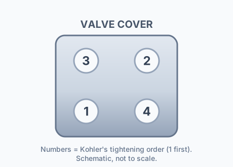
| valve cover fastener | 71 in-lb≈ 5.9 ft-lbHigh | 8 N·m (71 in. lb.). 4-position tightening sequence, diagrammed on p.49 (see the sequence diagram below) -- form 14 690 01 Rev. G, p.6. |
| retractable starter pawl drive plate center screw | 44–54 in-lbHigh | 5-6 N·m (44-54 in. lb.) -- form 14 690 01 Rev. G, p.32, reassembly step. |
| electric starter mounting screws (if equipped) | 84 in-lb= 7 ft-lbHigh | 9.5 N·m (84 in. lb.) -- form 14 690 01 Rev. G, p.51, reassembly step. |
| flywheel brake lever assembly screws (reassembly step) | 84 in-lb= 7 ft-lbHigh | 9.5 N·m (84 in. lb.). From the brake-lever reassembly step, not the main torque table -- form 14 690 01 Rev. G, p.50. |
| auto-choke arm assembly nuts to muffler (if equipped) | 75 in-lb≈ 6.3 ft-lbHigh | 8.5 N·m (75 in. lb.) -- form 14 690 01 Rev. G, p.54, reassembly step. |
| auto-choke arm assembly screws to carburetor (if equipped) | 20 in-lb≈ 1.7 ft-lbHigh | 2.3 N·m (20 in. lb.) -- form 14 690 01 Rev. G, p.54, reassembly step. |
| dipstick tube screw (extended dipstick) | 71 in-lb≈ 5.9 ft-lbHigh | 8 N·m (71 in. lb.) -- form 14 690 01 Rev. G, p.55, reassembly step. |
| engine cover insert Torx screws (if equipped) | 20 in-lb≈ 1.7 ft-lbHigh | 2.5 N·m (20 in. lb.) -- a rounding mismatch in Kohler's own printed table (2.5 N·m converts to ~22 in-lb, not 20), not a transcription… Why ›error: the auto-choke screws elsewhere in this table print the identical "20 in. lb." for a genuinely different 2.3 N·m. Reproduced exactly as printed. Form 14 690 01 Rev. G, p.55, reassembly step. |
| engine cover nuts (if equipped) | 71 in-lb≈ 5.9 ft-lbHigh | 8 N·m (71 in. lb.) -- form 14 690 01 Rev. G, p.55, reassembly step. |
2 specs not published — blade bolt / blade adapter / PTO fastener, oil filter What we found ›
- blade bolt / blade adapter / PTO fastenerGAP: not in this manual. Kohler's XT service manual defers entirely: "Refer to operating instruction of equipment that this engine powers" (p.1). Blade torque is a mower/equipment-manual spec, not an engine spec -- do not use a Kohler engine figure for it.
- oil filterGAP: XT engines have no oil filter -- the word "oil filter" does not appear anywhere in form 14 690 01 Rev. G.
Kohler XT tightening SEQUENCES (oil pan, cylinder head, valve cover)
Kohler's XT torque table gives a single number for the oil pan screws, the cylinder head fasteners and the valve cover fasteners, but each of those is actually a multi-bolt pattern that has to be brought down in a specific numbered order -- printed only as a diagram, not as text. The three diagrams below are redrawn as schematics from Kohler's own service manual -- the numbers are Kohler's order, not a trace of the artwork.
Oil pan screw sequence -- XT-7 family (6 screws, top) vs XT-6 family (7 screws, bottom)
The XT-7/XTR-7/XT775/XT8 family (top diagram) uses 6 oil pan screws, torqued to 14.7 N·m (130 in-lb) in the numbered order 1 through 6. The XT-6/XTR-6/XT6.5/XT6.75/XT650/XT675 family (bottom diagram) uses 7 screws, torqued to 11.0 N·m (98 in-lb) in the numbered order 1 through 7. The two patterns share the same general bolt-circle layout but are not the same sequence -- follow the diagram for your specific family.
Cylinder head bolt sequence (4 bolts)
Kohler's 4-bolt head diagram numbers the bottom-left bolt 1, the top-right bolt 2, the top-left bolt 3, and the bottom-right bolt 4 -- tighten in that 1-2-3-4 order, in the two increments given in the table above (14 N·m/123 in-lb first, 27.8 N·m/246 in-lb final).
Valve cover bolt sequence (4 bolts)
The valve cover uses the identical 4-position numbering as the head bolts above -- bottom-left is 1, top-right is 2, top-left is 3, bottom-right is 4 -- torqued to 8 N·m (71 in-lb).
Sources for this section (1)
What is the head bolt torque on a Kohler XT650 or XT675?
Kohler's XT service manual (form 14 690 01 Rev. G, p.6) specifies the cylinder head fastener in two steps: 14 N·m (123 in-lb) first, then a final pass to 27.8 N·m (246 in-lb), following the 4-bolt sequence diagrammed on p.49. This applies across the whole XT-6/XT-7 line, including the XT650 and XT675.
What's the flywheel nut torque on a Kohler XT engine?
51.5 N·m (38 ft-lb), per the XT torque table (p.6). Hold the flywheel with a strap wrench, not an impact gun -- Kohler's own install steps (p.51) call for a dry taper.
Does the oil pan screw torque differ between the XT650 and the XT775?
Yes. The XT-6 family (XT-6, XTR-6, XT6.5, XT650, XT6.75, XT675) uses 7 oil pan screws at 11.0 N·m (98 in-lb); the XT-7 family (XT-7, XTR-7, XT775, XT8) uses 6 screws at 14.7 N·m (130 in-lb). It's the only torque figure that differs between the two bore families in this manual.
What torque does a Kohler XT spark plug take?
27 N·m (20 ft-lb), per the XT torque table (form 14 690 01 Rev. G, p.6).
What is the blade bolt torque on a Kohler XT650 or XT675?
Kohler's XT service manual doesn't publish one. The word "blade" appears only once in the whole document, as "flat blade screwdriver" -- the manual's own cover page defers to the equipment: "Refer to operating instruction of equipment that this engine powers." Blade torque on an XT-powered mower is a mower-manufacturer spec (Toro, Husqvarna, MTD, Cub Cadet, Craftsman, etc.), not a Kohler engine spec -- check your mower's own manual rather than applying a figure from this page.
Related lookups
- Honda GX Series Engine Torque Specs
- Briggs & Stratton Engine Torque Specs
- Predator (Harbor Freight) Engine Torque Specs
- Kohler Engine Torque Specs
- Kohler K-Series & Magnum Engine Torque Specs
- Kohler Command PRO 999cc (CH940-CV1000) Torque Specs
- Kawasaki Engine Torque Specs
- Honda GCV Series Engine Torque Specs
- Stihl Engine Torque Specs
- Husqvarna Chainsaw Torque Specs
- Echo Engine Torque Specs
- Tecumseh Engine Torque Specs
- Onan Engine Torque Specs
- LCT Engine Torque Specs
- Carburetor, Muffler & Blower Housing Specs
- Snow Blower Shear Pin Sizes
- All Small Engine Specs
- Wrench & Socket Size Finder
Loading interactive lookup…